Fine Screen and Pre MBR Screens
SMH– Multi Brushes Screen
SSW– Step Screen
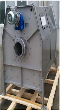
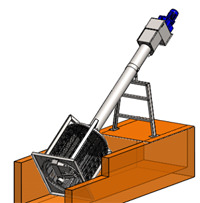
CFC– Screw Screen for installtion inchannel or with stinless steel tanks
CFV- Vertical screw screen compactor
EFD- Rotary Screen
IFD- Internally fed Rotary Drum Screen
GTR- RotaryOTARY Drum Screw Screen
Screenings Conveying:
CCS – Horizontal and inclined shaftless screw conveyor
CCS/V – Vertical shaftless screw conveyor
Screenings Treatment:
CP – Shaftless spiral conveyor and compactor
CPP - Screw press with screenings washings
Grit separation and washing
VXGR: Vortex grit separator
CDS : Grit classifter with shaftless spiral
CDL : Grit washer
Complete mechanical pre-treatment stations
WAU2 : Screen and grit
WAU3 : Screen, grit and grease
GGR2/N: Cimplete pre-treatment Station
Series 10 and series 30 - complete pre treatment stations untill 30 mc/h
MCB: Cimplete pre treatment station for comunities
Septic tanks receipt and treatment stations:
SAU1 : Receipt and screen complete Station
SAU2 : Receipt, Screen, AND grit Separation Complete station
SAU3 : Receipt, Screen, grit, screen grit and grease removal station
Sludge Treatment Treatment and conveying:
SD–SDF- Filtering and dewatering unit. Sludge Thickener and screw Press
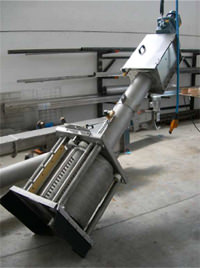
The Screw screen is an ideal solutiesion for small to medium installation. One machine carries out the screening, transportation and compaction of the screenings. The fine filtration may be circular holes (2 to 6mm) or trapezoidal profile with spacing from 0.5 to 2mm.
The Screw screen can be provided for direct installation in a concreate channel or in a stainless steel tank withh effluent inlet pipe connection.
The principle of operation is as follows:
The semi-circular screen retains soilds as the liquid passes them. The solids clog the holes and cause a rise in the level of the effluent causing a differential between the level of the provides the auger start signal detects the increase in absolute or differential water level. As the auger rotates, brushes fixed on the lower part of the auger clean the screening profile. The auger then transports the screenings to the compaction area. Compaction is achieved byreducing the auger pitch. The compacted soilds exit the screen out the discharge chute.
| Theoretical Flow Rates(*) | |||||||
| CF/CFCMODEL | 20 | 30 | 40 | 50 | 60 | 70 | |
| Screen Basket | m3/h | ||||||
| WW | 0,25mm | 20 | 35 | 55 | 120 | 200 | 290 |
| 0,5mm | 45 | 60 | 85 | 190 | 275 | 370 | |
| 1mm | 75 | 90 | 120 | 265 | 360 | 530 | |
| 2mm | 85 | 105 | 150 | 310 | 415 | 670 | |
| @ | 3mm | 100 | 125 | 180 | 320 | 465 | 740 |
| 5mm | 140 | 162 | 268 | 396 | 590 | 950 | |
| 6mm | 160 | 198 | 300 | 435 | 600 | 980 | |
| 8mm | 180 | 220 | 350 | 480 | 650 | 1000 | |
SSW– Step Screen
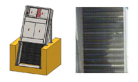 The step screen is a viable solution for medoum and large plants. It is in fact a system that exploits the principle of fixed and moving lamellas equidistant between them. The distance between the lamellas represants the spacing of the screen itself.The step screen is installed
inside of a chhanel with an inclination from 45 to 55. The effluent liquid passes through the screen, while the soilds settele on the steps.
The eccentric motion of the moving lamells lifts the screenings that are desposited on the fixed lamellas. The movements of the moving segments is ensured by a transmission system (and cam shaft) connecyed to a geared motor unit. The distance between the lamellas and consequently the screen spacing in steps can be from 3 to 6 mm. As the screening profile is composed of bars (lamellas). the open area is importants and consequently the headloss is reduced. The screen height is adapted for the headloss is reduced. The screen height is adapted for the step screen to bbe installed in channels of considerable depth.
The step screen is a viable solution for medoum and large plants. It is in fact a system that exploits the principle of fixed and moving lamellas equidistant between them. The distance between the lamellas represants the spacing of the screen itself.The step screen is installed
inside of a chhanel with an inclination from 45 to 55. The effluent liquid passes through the screen, while the soilds settele on the steps.
The eccentric motion of the moving lamells lifts the screenings that are desposited on the fixed lamellas. The movements of the moving segments is ensured by a transmission system (and cam shaft) connecyed to a geared motor unit. The distance between the lamellas and consequently the screen spacing in steps can be from 3 to 6 mm. As the screening profile is composed of bars (lamellas). the open area is importants and consequently the headloss is reduced. The screen height is adapted for the headloss is reduced. The screen height is adapted for the step screen to bbe installed in channels of considerable depth.
EFD - Rotary Screen
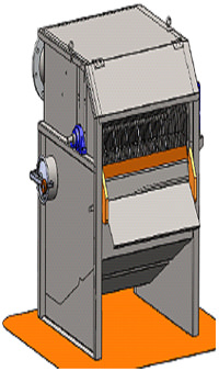 The efflient in to the headbox, designed to distribute effliuent meshes
may be circular holes (2 to 6mm) or trapezoidal profile from 0.25 to 4 mm.
The suspended solid particles are in contact with the drum. The slow
rotation motion of the drum then carries the particles to the outside
edge of the clrum, where a blade then removes the solids.
The efflient in to the headbox, designed to distribute effliuent meshes
may be circular holes (2 to 6mm) or trapezoidal profile from 0.25 to 4 mm.
The suspended solid particles are in contact with the drum. The slow
rotation motion of the drum then carries the particles to the outside
edge of the clrum, where a blade then removes the solids.
The fillered water enters inti top of the drum, only to exit again through the bottom,
thus acting as a from of wash water from the drum surface. A spay nozzle backwash system
is installed inside the drum to complete the washing
Filtration surface after every complete rotation is totally clean
(not clogged) and ready to repeat the cycle.
| Theoretical Flow Rates(*) | |||||||
| MODEL | 20 | 30 | 40 | 50 | 60 | 70 | |
| m3/h | |||||||
| WW | 0,25mm | 8 | 36 | 44 | 60 | 90 | 115 |
| 0,50mm | 14 | 62 | 68 | 110 | 150 | 205 | |
| 0.75mm | 17 | 85 | 92 | 148 | 215 | 275 | |
| 1.00mm | 20 | 102 | 110 | 186 | 265 | 345 | |
| 1.25mm | 23 | 115 | 120 | 205 | 300 | 385 | |
| 1.50mm | 26 | 134 | 155 | 230 | 340 | 435 | |
| 2.00mm | 30 | 140 | 185 | 250 | 365 | 465 | |
| 2.50mm | 33 | 160 | 205 | 265 | 375 | 480 | |
IFD - Internally FED Rotary Drum Screen
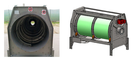
The Drum-Screen has a solid, Stainless steel unibody construction, a screening cylinder with interchangeable screening drum.
A standard speed drive electric gear motor rotates the drum screening cylinder assembly at 8 rpm. The screening cylinder rotates on four fully engineered wheels.
Interchangeable drum screen, of stainless steel wedge wire mesh/ perforated holes, from 0,25 to 6 mm provide the best screening/ Solids capture performance in all screening applications.
The liquid in the headbox/distribution chamber is directed onto the internal rotating surface of the screen. Solids remain on the surface of the screen while the liquid goes through the screen media.
As the screen rotates, the solids roll on the face of the screening cylinder and are intercepted by the diverter flights. The diverter flights are mounted spirally, with the spiral pointing cylinder rotates, the solids drop off one diverter flight to the cylinder. The Solids can drop off into a container; conveyor chute or sludge dewatering device for further processing to reduce the water content and/ or increase the solids dryness. The unibody design of the DRUM-SCREEN incorporates a drainage collection area including a flanged discharge pipe that direct the treated water to a tank, channel, or pit or on through further piping.
The spraying/ backwash system (inside or out) located on the upper half of the unit, will wash off any solids, grease or other materials sticking to the face of the screening media and thus keep the inside of the cylinder clean. The backwash can be set manually, or programmed to operate on an as needed basis.
GTR - Rotary Drum Screw Screen
Working Principle
GTR Screens with or without compactor are used for Solid-liquid separation for high flow rate and combie two operations: filtration and compaction.
They feature a screen basket, perforated sheet or wedge wire, that act as a filter and rotate with the transport screw, followed by a tyransport section that ends with a compacting/ dewatering module that can be provided with a chute or a bagging system.
A shafted screw conveys the screening to the compacting/ dewatering section where both the volume and the weight are reduced (up to 40%).
Manufacturing Features
Screw: stainless steel AISI 304/ 316
Structure: stainless steel AISI 304/316
Length: The total length may be varied to meet the plant layout specifications
Trough Protection: Bolted stainless steel wearing bars.
Screen Basket: Perforated sheet or wedge wire
Screen Basket Cleaning: Brushes and spray nozzless
| Main Dimensions | |||||||||||
| GTR TYPE | 8 | 10 | 12 | 14 | 16 | 18 | 20 | 24 | 26 | 30 | |
| SCREEN BASKET | THE ORETICAL FLOW RATEE (GTR and GTR - D have same capacity) m3/ h |
||||||||||
| 0,5mm | 108 | 235 | 290 | 430 | 580 | 790 | 940 | 1460 | 1820 | 2050 | |
| 1mm | 270 | 400 | 470 | 720 | 970 | 1470 | 1750 | 2420 | 2998 | 3210 | |
| 2mm | 290 | 490 | 720 | 936 | 1420 | 1820 | 2010 | 2780 | 3310 | 3519 | |
| 3mm | 325 | 400 | 550 | 890 | 1200 | 1550 | 1867 | 2450 | 2710 | 3202 | |
| 6mm | 690 | 000 | 1310 | 1800 | 2080 | 3400 | 4510 | 5620 | 7120 | 8020 | |
| 8mm | 810 | 1020 | 1910 | 2460 | 3110 | 3900 | 4950 | 5990 | 7510 | 8980 | |